

Every SE builds a campus network on a whiteboard at some point. The customer has a new building, a network refresh, or an acquisition that requires integrating a new site. They want a reference architecture - not a product pitch, not a features comparison - an architecture that they can hand to their network team and say “build this.”
This post provides that reference architecture. It covers the standard 3-tier campus design with a security overlay, ISE node placement, firewall positioning, wireless security, Layer 2 hardening, 802.1X/MAB deployment, and SD-Access for modern campuses. At the end, there is a bill of materials template for a 500-user campus that SEs can adapt for proposals.
The 3-Tier Campus Design with Security Overlay
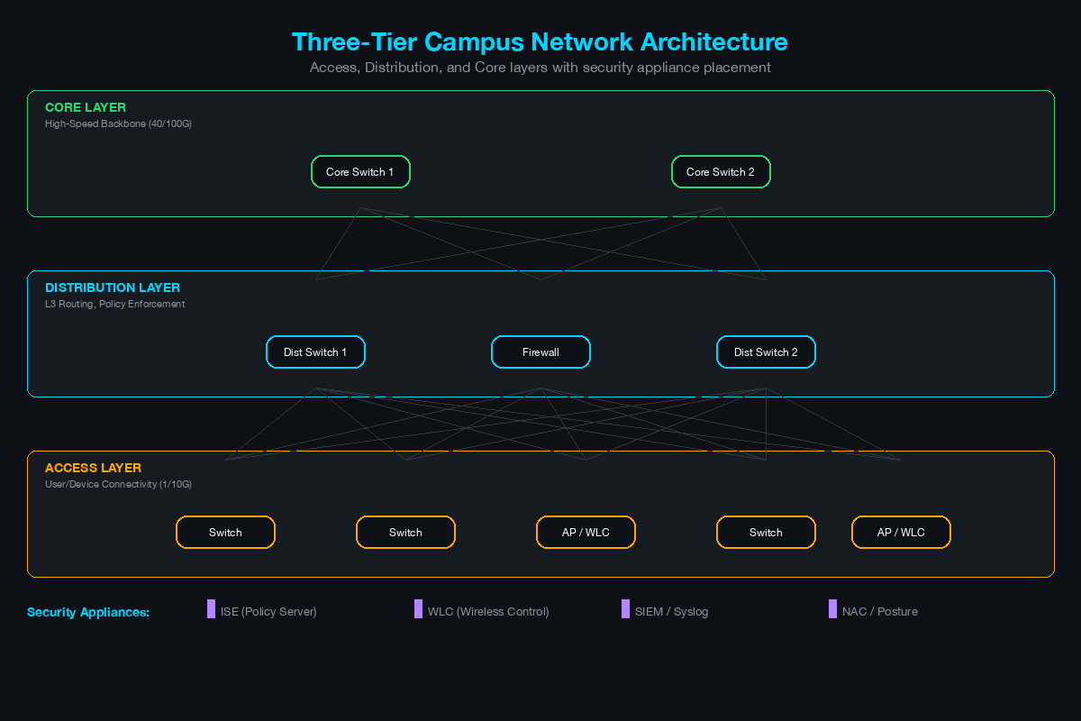
The 3-tier campus model - access, distribution, core - remains the foundation of campus network design. The security overlay adds controls at each tier without changing the fundamental traffic flow architecture.
                          [Internet]
                              |
                        [Perimeter FW]
                              |
                     =====================
                     |    CORE LAYER     |
                     |  (2x Core Switches) |
                     =====================
                        /           \
               ============      ============
               | DIST SW-A |      | DIST SW-B |
               | (Building 1)|    | (Building 2)|
               ============      ============
                /    |    \         /    |    \
            [AS-1] [AS-2] [AS-3] [AS-4] [AS-5] [AS-6]
             Access Layer Switches (48-port PoE+)
              |      |      |      |      |      |
           [Users] [APs] [IoT]  [Users] [APs] [Printers]

                     [Data Center Block]
                           |
                     [Internal FW]
                           |
                     [Server Farm]
                     [ISE PAN/MnT]
                     [ISE PSN-1, PSN-2]
                     [WLC-1, WLC-2]
                     [DNS, DHCP, NTP]
Access Layer: Every port facing an endpoint. This is where 802.1X/MAB enforcement happens, where DHCP snooping, DAI, and IPSG are enabled, and where VLANs are assigned dynamically based on ISE policy. PoE+ powers IP phones, APs, and IoT devices.
Distribution Layer: Aggregates access switches, performs inter-VLAN routing, and enforces policy with ACLs or SGACLs. In campus designs with TrustSec, the distribution layer is where SGT enforcement typically occurs for north-south traffic between access and the data center.
Core Layer: High-speed backbone connecting distribution blocks, data center, WAN edge, and internet edge. The core should be as simple as possible - fast forwarding, no policy enforcement, no ACLs. Security controls belong at the access and distribution layers.
ISE Node Placement: PAN, MnT, and PSN
ISE is the policy engine for the entire campus security architecture. Getting the node placement right is critical for both performance and redundancy.
ISE Personas
Cisco ISE separates functionality into three personas that can run on the same appliance (small deployments) or on dedicated nodes (enterprise deployments):
- PAN (Policy Administration Node): The management interface where administrators configure policies, manage device groups, and define authorization rules. Only one PAN is active at a time (primary/secondary for HA).
- MnT (Monitoring and Troubleshooting Node): Collects all RADIUS logs, audit data, and profiling data. Used for reporting, troubleshooting failed authentications, and compliance auditing.
- PSN (Policy Service Node): Handles real-time RADIUS/TACACS+ authentication requests from network devices. This is the performance-critical persona - it must respond to authentication requests within milliseconds.
Placement Strategy
[Building 1]                    [Building 2]
  Access Switches ------\         Access Switches ------\
  (RADIUS to PSN-1)      \       (RADIUS to PSN-2)      \
                          |                               |
                    [PSN-1]                         [PSN-2]
                    (Local to Bldg 1)               (Local to Bldg 2)
                          \                             /
                           \                           /
                            ===========================
                            |    Data Center           |
                            |   [PAN - Primary]        |
                            |   [PAN - Secondary]      |
                            |   [MnT - Primary]        |
                            |   [MnT - Secondary]      |
                            ===========================
PSN placement: Deploy PSNs as close to the network access devices as possible. If RADIUS traffic must cross a WAN link to reach a PSN, authentication latency increases and WAN failure means no new authentications. For a multi-building campus, deploy at least one PSN per building or per distribution block. Each access switch should have a primary and secondary RADIUS server configured - primary PSN in the local building, secondary PSN in the adjacent building.
PAN/MnT placement: These can be centralized in the data center. PAN handles administrative configuration (not real-time authentication), so latency is not critical. MnT collects logs asynchronously.
Sizing: For a 500-user campus, a single ISE VM with all three personas can handle the load. For campuses above 1,000 users, separate the PSN onto its own node. ISE supports up to 50 nodes in a deployment for large enterprises.
Firewall Positioning: Perimeter and Internal
Perimeter Firewall
The perimeter firewall sits between the core layer and the internet edge. Every campus needs one. This firewall handles:
- Inbound traffic filtering from the internet
- Outbound traffic filtering and URL categorization
- VPN termination for remote users (unless a dedicated VPN concentrator is deployed)
- Intrusion prevention (IPS) for north-south traffic
- Malware inspection for downloaded files
For a 500-user campus, a Cisco Secure Firewall (FTD) 2100 or 3100 series in HA pair handles the throughput requirements with all security services enabled.
Internal Segmentation Firewall
The internal firewall is often overlooked but critical for security-mature deployments. It sits between the campus core and the data center (or server farm), inspecting east-west traffic between user VLANs and server VLANs.
[Campus Core] --- [Internal FW] --- [Data Center Switches] --- [Servers]
This firewall enforces:
- Application-level access control between user segments and server segments
- IPS inspection on internal traffic (where most lateral movement occurs)
- Logging and visibility for compliance (PCI DSS, HIPAA)
Customers frequently push back on internal firewalls (“we trust our internal network”). The counter-argument: every breach case study in the last decade involves an attacker who was already inside the perimeter. The internal firewall exists to catch lateral movement that the perimeter firewall will never see.
Wireless Security Architecture
Components
[Wireless Clients]
       |
       | (802.11ax / Wi-Fi 6E)
       |
  [Access Points]
       |
       | (CAPWAP tunnel to WLC)
       |
  [Wireless LAN Controller (WLC)]
       |
       | (RADIUS to ISE)
       |
  [Cisco ISE PSN]
       |
       | (CoA / RADIUS)
       |
  [Access Switch]
       |
       | (VLAN assignment based on ISE policy)
       |
  [Network]
WLC placement: For a single-campus deployment, deploy two WLCs in HA (active/standby or SSO) in the data center or server room. APs connect to the WLC via CAPWAP tunnels over the existing wired network - no special cabling required for the wireless overlay.
AP placement: Conduct a predictive site survey (using Ekahau or similar) before deployment. Rule of thumb for office environments: one AP per 2,500–3,000 square feet, adjusted for wall materials, ceiling height, and density requirements. A 500-user campus in a standard office building typically needs 40–60 APs.
Wireless Authentication
Corporate SSID (802.1X/EAP): The primary SSID for managed devices. Uses 802.1X with EAP-TLS (certificate-based - strongest) or PEAP-MSCHAPv2 (credential-based - easier to deploy). RADIUS authentication is handled by ISE, which assigns the user to a VLAN and applies an SGT based on their identity and device posture.
Guest SSID (Web Authentication): A separate SSID for guest devices. Uses a captive portal (hosted on ISE or WLC) for self-registration or sponsor-approved access. Guest traffic should be isolated to a dedicated VLAN that routes directly to the internet through the perimeter firewall - never through the internal campus network.
IoT/BYOD SSID (MAB or PPSK): For devices that cannot perform 802.1X. Use ISE profiling to identify device types (cameras, sensors, medical devices) and assign them to restricted VLANs with limited network access.
Layer 2 Security at the Access Layer
Three features should be enabled on every access layer switch. They work together and should be deployed as a set.
DHCP Snooping
DHCP snooping inspects DHCP messages on the switch and builds a binding table mapping IP addresses to MAC addresses on each port. Ports connected to legitimate DHCP servers are configured as “trusted” - all other ports are “untrusted” and can only send DHCP client messages.
This prevents rogue DHCP server attacks where an attacker sets up a DHCP server to assign clients a malicious default gateway (enabling man-in-the-middle attacks).
Dynamic ARP Inspection (DAI)
DAI validates ARP packets against the DHCP snooping binding table. If a host sends an ARP reply claiming to be the default gateway but the IP-to-MAC mapping does not match the DHCP snooping table, DAI drops the packet.
This prevents ARP spoofing/poisoning attacks - one of the most common Layer 2 attack techniques used for man-in-the-middle positioning on local networks.
IP Source Guard (IPSG)
IPSG filters traffic on each untrusted port, allowing only traffic from the IP address assigned to that port (as recorded in the DHCP snooping binding table). If a host attempts to send traffic with a spoofed source IP, IPSG drops it.
Together, DHCP snooping, DAI, and IPSG create a Layer 2 security baseline that prevents the most common local network attacks: rogue DHCP, ARP spoofing, and IP spoofing.
802.1X and MAB Deployment Strategy
The Authentication Sequence
Every access port should be configured with the following authentication sequence:
802.1X (primary): When a device connects, the switch sends an EAP-Request-Identity frame. If the device has a supplicant (Windows, macOS, Linux - all have built-in supplicants), it responds with EAP credentials. The switch relays the authentication to ISE via RADIUS. ISE authenticates the user/device and returns an authorization result (VLAN, SGT, dACL).
MAB (fallback): If the device does not respond to EAP within the configured timeout (typically 30 seconds), the switch falls back to MAB. It sends the device’s MAC address to ISE as the username/password in a RADIUS request. ISE looks up the MAC address in its endpoint database and returns an authorization result. This is how printers, cameras, IP phones, and IoT devices authenticate.
Guest VLAN / Web Auth (final fallback): If both 802.1X and MAB fail, the port can be configured to assign the device to a restricted guest VLAN with captive portal access for self-registration.
Phased Deployment
Do not deploy 802.1X in enforcement mode on day one. The phased approach:
Phase 1 - Monitor Mode: Enable 802.1X on all ports but do not restrict access on authentication failure. All devices connect regardless of authentication result. ISE collects data about which devices authenticate successfully, which fail, and which use MAB. Run this phase for 2–4 weeks.
Phase 2 - Low-Impact Mode: Begin restricting access for devices that fail authentication. Use a pre-auth ACL that allows DHCP, DNS, and limited network access before authentication completes. Devices that authenticate successfully get full access. Devices that fail get the restricted pre-auth ACL. This phase surfaces any remaining devices that need to be added to the MAB database.
Phase 3 - Closed Mode (Full Enforcement): Ports deny all traffic until authentication succeeds. This is the target state. Only reach this phase after Monitor Mode and Low-Impact Mode have identified and resolved all authentication issues.
SD-Access: The Modern Campus Option
For customers building a new campus or performing a full network refresh, Cisco SD-Access provides an overlay-based approach that simplifies segmentation and policy enforcement.
SD-Access Architecture
[Cisco DNA Center] --- Management Plane (automation, assurance, policy)
        |
        v
[Control Plane Nodes] --- LISP map server/map resolver
        |
        v
[Border Nodes] --- Connect campus fabric to external networks (DC, WAN, Internet)
        |
        v
[Edge Nodes] --- Access layer switches running VXLAN fabric
        |
        v
[Endpoints] --- Authenticated via ISE, assigned to virtual networks (VNs)
Key advantage: SD-Access uses VXLAN to create a network fabric where endpoints are assigned to virtual networks (VNs) based on identity. Macro-segmentation happens between VNs. Micro-segmentation happens within VNs using SGTs. The entire policy is managed from DNA Center and ISE - no manual VLAN configuration on individual switches.
When to propose SD-Access vs traditional: SD-Access makes sense for greenfield deployments, campus refreshes with 500+ users, or environments where segmentation complexity has outgrown manual VLAN/ACL management. It does not make sense for small single-building deployments or brownfield environments where existing switches are not SD-Access capable.
Bill of Materials Template: 500-User Campus
The following BOM template covers a 500-user, two-building campus with full security stack. Adapt quantities based on the customer’s specific layout, density, and redundancy requirements.
| Category | Component | Quantity | Notes |
|---|---|---|---|
| Access Layer | Catalyst 9300-48P (PoE+) | 14 | 48-port, Network Advantage license |
| Distribution | Catalyst 9500-24Y4C | 2 | StackWise Virtual pair |
| Core | Catalyst 9500-48Y4C | 2 | Omit if collapsed core design |
| Perimeter FW | Secure Firewall 3110 | 2 | HA pair, Threat + Malware license |
| Internal FW | Secure Firewall 2130 | 2 | HA pair (optional, recommended) |
| WLC | Catalyst 9800-40 | 2 | HA SSO pair |
| Wireless APs | Catalyst 9136AXI | 50 | Wi-Fi 6E, based on survey |
| ISE | ISE 3.x VM | 3 | 1 PAN/MnT, 2 PSN |
| ISE Licensing | ISE Advantage | 500 | Per-endpoint, 3- or 5-year term |
| DNA Center | DNAC Appliance or VM | 1 | Required for SD-Access; optional otherwise |
| UPS/Power | Rack UPS | Per MDF/IDF | Size per switch power draw |
| Cabling | Cat6A | Per survey | Minimum for PoE+ and 10G AP uplinks |
Licensing Notes
ISE licensing tiers determine available features:
- ISE Base: 802.1X, MAB, guest access, basic profiling
- ISE Plus: Base + BYOD, posture assessment, threat-centric NAC
- ISE Advantage: Plus + TrustSec SGT, pxGrid, Rapid Threat Containment
For most secure campus deployments, ISE Advantage is required to enable TrustSec and pxGrid integration with the firewall and other security tools.
Putting It Together: The SE Whiteboard Session
When presenting this architecture to a customer, the whiteboard session should follow this sequence:
Start with the physical layout: Draw the buildings, floors, and MDF/IDF locations. This grounds the architecture in the customer’s real environment.
Overlay the 3-tier design: Map access switches to IDFs, distribution to MDFs, and core to the primary data center or server room.
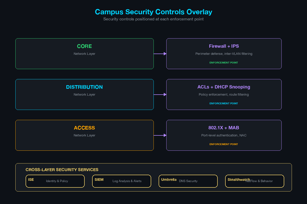
Add the security controls layer by layer: Start with Layer 2 (DHCP snooping, DAI, IPSG), then 802.1X/MAB, then firewall positioning, then ISE placement. Each layer addresses a specific threat vector - explain the threat before introducing the control.
Show the wireless overlay: Draw the WLC-to-AP relationship and explain the authentication flow for corporate, guest, and IoT SSIDs.
End with the segmentation model: Show how VLANs, ACLs, or TrustSec/SGTs enforce segmentation across the entire campus. Connect this to the customer’s compliance requirements (PCI, HIPAA, or general risk reduction).
The goal is not to present every component on this page. The goal is to present the architecture that matches the customer’s maturity, budget, and operational capacity - and to provide a clear upgrade path for the components they defer to a future phase.
Related Posts in This Series
- Network Segmentation: VLANs, Microsegmentation, and TrustSec - Deep dive into the segmentation layer that underpins campus security
- Cisco ISE vs Aruba ClearPass vs Forescout - Compare the NAC platforms at the heart of campus access control
- Running a Cisco ISE POC: Timeline, Scope, and Gotchas - Practical guide when your campus design leads to an ISE proof of concept
- IoT Security Architecture for Manufacturing and Healthcare - Extend your campus architecture to secure IoT and OT devices
- How to Whiteboard a Zero Trust Architecture in 10 Minutes - Overlay zero trust principles onto your campus reference design
Practice with free flashcards, quizzes, and hands-on lab scenarios at cciesec.it-learn.io — built specifically for the CCIE Security v6.1 written (350-701 SCOR) and lab exam.


